Yaesu VX-170 Modifications
Other keywords: vx170, mods, out of band, transmit, HT, handie-talkie
Standard disclaimer:
This advice is offered without warranty. Use it entirely at your own
risk. It's not my fault if you damage your radio. You should not
transmit illegally.
By
Alan Silverstein,
N0MFW,
ajs@frii.com.
Last update: July 7, 2011
This describes my experience in July, 2007, with a new unit. Modifying
the radio at least allows transmitting out of the ham bands ("for
emergency use only"), possibly other features too, not sure. The recipe
follows.
-
Place the radio face-down with the antenna pointing away from
you. Call that direction "north".
-
Remove the battery pack.
Below where the battery was, you should see a large, rectangular, black
plastic cover on the left (west) side, with the longer dimension
north/south. There's a small notch in one corner; in my case, on the
southwest (lower left). This is an adhesive-backed, stiff sheet of
plastic, probably part of the waterproofing. It's blank, unlike the
label to the right of it.
Do not remove the screws to the south, that's not necessary.
-
Peel up the plastic cover.
I used a jeweler's screwdriver, carefully, and set the cover aside
sticky-side-up.
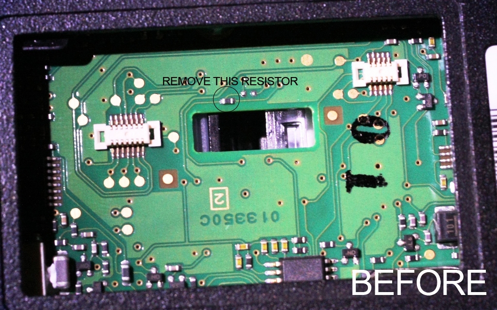
Now through the hole, you should see a green PC board with a rectangular
hole cut into it, with the long dimension north/south. There are white
connectors northwest and southwest of this hole. Just west of the
cutout, some wire traces run north/south. At least one has a
surface-mount zero-ohm "resistor" (jumper) in the line. The jumper is
tiny, maybe 1 mm across. In my case, a second pair of solder dots just
to the northwest were already open (visible).
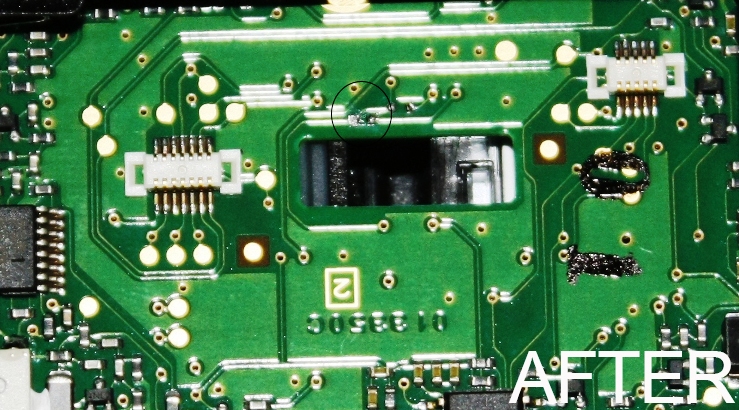
(Photos courtesy of Chris Terry, K9WWV:)


-
Remove both jumpers.
I did this by warming up a pencil-tip soldering iron and briefly
touching it to one side of the jumper while pushing gently sideways.
This unsoldered one side. I tried to break loose the other side with
needle-nose pliers, and ended up peeling back some of the wire. So,
either unsolder both sides, cut the jumper free after one side is
unsoldered, or leave it attached on one side but "open" (perhaps with a
bit of tape below it for insulation).
Note: I found it helpful to wear a binocular magnifier while doing this
under a bright light.
-
Reinsert the battery pack and turn the radio over to face you.
"What about the plastic cover?" Test first, then replace it, see below.
-
Turn on:
Press and hold the PTT and Moni switches (on the left side) while
switching on the radio (rotate the volume knob). The display should say
"SETRST".
-
Rotate the lower dial knob to display "ALLRST", then press "F".
-
Modification complete!
Turn off the radio, remove the battery pack, carefully replace the
sticky plastic cover below it, and reinstall the battery pack.
Note: This webpage exists because I hunted the web looking for this
information before I bought a new HT. I found what I needed, and that
was great, but it was so brief and poorly written that it was hard to
understand, and thus scary to use. There was a snapshot, too, but it
was pretty fuzzy. I hope you will find the preceding verbal description
clear and usable without a picture.
PS: Info contributed by Bernard
in France, July 2011:
...just bought a FT-270E which is limited in RX and TX between 144.000
and 146.000. Inside the radio, two (2) resistors were soldered the same
place as VX-170. I understood what are for the 2 resistors.
The first one, the one which is not mounted on your pictures, is linked
to the RX bandwith. After de-soldering it and reset, the radio extends
the RX bandwith betwenn 137.000 and 148.000. In this case, if I press
the PTT button outside the 144.000 to 146.000 bandwith, "ERROR" is
displayed by the radio.
The second one, the one which is mounted on your top of page picture, is
linked to the TX bandwith. After de-soldering it and reset, the radio
extends the TX bandwith betwenn 137.000 and 148.000. In this case, if I
press the PTT button outside the 144.000 to 146.000 bandwith, radio is
working properly.

